Brachytherapy HDR afterloader examination for measurement source position lagging effect
Vladimir Stserbakov,
Estonia
PO-1804
Abstract
Brachytherapy HDR afterloader examination for measurement source position lagging effect
Authors: Vladimir Stserbakov1
1North-Estonia Medical Center Foundation , Radiotherapy, Tallinn, Estonia
Show Affiliations
Hide Affiliations
Purpose or Objective
Brachytherapy QA programme
suppose verification accuracy of applicator library built-in into
treatment planning system, which is provided by the manufacture. One method to
create the user` own model of brachytherapy applicator is to measure mechanical
characteristics of afterloader and applicators separately and based on that to
calculate parameters/behavior of joined the afterloader-applicator connection. The
purpose of this work is do all required measurements for in clinical use
Flexitron (Elekta) afterloader or, as first step/side of QA project, to
investigate effect of radiation source position lagging from its nominal d-well
place caused by braking strength affected on radiation source movement inside brachytherapy applicator.
Material and Methods
In figure you can see the idea of measurement setup
based on using manufacture (Flexitron, Elekta) source position check ruler
5. Mechanical resistance to moving of the source 4 through source travelling
path makes mandrel 3, inserted into source travel path, which is connected with
elastic parts 2 (in this role can be used, for example, rubber strips,
springs or whatever) for producing needed increasing resistance force. Later,
when source lag was measured, the breaking force scaled by strength measuring
tool 1 (for this case we used Scale 500g 0.1g LCD
Display Digital Weight Measuring Tool). To perform more
accurate measurements for different strength ranges we use 3 types of
elastic parts: „hard” – for 0-300 g force; „moderate” – for 0-100 g and „soft”-
for 0-30 g. For all these elastic parts types breaking force should
be produced in source position range of ruler from ”200” source dwell-position
to “300” (i.e. for clinically most popular gynecologic applicators).
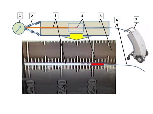
Figure. Scheme of setup for measurement of source
position lagging effect. 1- Strength measuring tool; 2 – elastic parts; 3 –
needle mandrel; 4 – radiation source; 5 – source position check ruler; 6 – source
cable; 7 – afterloader.
Results
On the table
you can see averaged value for Δ (radiation source position deviation/lag
from its nominal location) measured with 3 different hardness of elastic parts,
which correspond ≤30g, ≤100g and ≤300g braking force ranges. As you see, lag
effect is more distinctive (Δ= 1.5 mm) for the first 20 g braking
strength, and for the rest part its approximately linear up to “obstruction”
source cable strength value ~300 g with rate 0.9 mm/100 g. Source cable
strength range values (as we now preliminary estimate) for Ring (≤50g) and Venezia (≤120g)
applicators are mentioned too in the table.
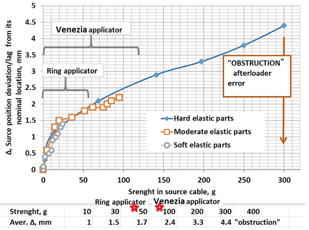
Table. Measured Δ values (radiation source position deviation/lag
from its nominal place) in mm. Ù 50
g, Ù100 g
- braking strength ranges of Ring and Venezia
applicators correspondingly.
Conclusion
Measured values for source position lag effect
for known cable strength are essential basic data for calculation/creation
user’ model of library applicator in quality assurance procedure for
verification manufacture applicator library files.